Mitsubishi Triton Manuals Wiring Diagram
- Mitsubishi Triton Manuals Wiring Diagrams
- Ideal 7228 90 User Manuals Wiring Diagram
- Twizy Manuals Wiring Diagram
Mitsubishi Triton L200. Electrical And Owners Manuals 2003 Mitsubishi Lancer. WORKSHOP REPAIR MANUAL MITSUBISHI MONTERO SPORT WIRING DIAGRAM.
- If you are looking for a ebook Mitsubishi triton manuals wiring diagram in pdf format, then you have come on to the faithful site. We presented full option of this.
- Nov 15, 2017 - This is the Highly Detailed factory service repair manual for the2006 MITSUBISHI TRITON, this Service Manual has detailed illustrations as well.
This is the Highly Detailed factory service repair manual for the2006 MITSUBISHI TRITON, this Service Manual has detailed illustrations as well as step by step instructions,It is 100 percents complete and intact. They are specifically written for the do-it-yourself-er as well as the experienced mechanic.2006 MITSUBISHI TRITON Service Repair Workshop Manual provides step-by-step instructions based on the complete dis-assembly of the machine. It is this level of detail, along with hundreds of photos and illustrations, that guide the reader through each service and repair procedure.
Complete download comes in pdf format which can work under all PC based windows operating system and Mac also, All pages are printable. Using this repair manual is an inexpensive way to keep your vehicle working properly. Model Covers: Mitsubishi KA4 Mitsubishi KB4 Mitsubishi KB8 Service Repair Manual Covers: General Engine Engine Mechanical Engine Lubrication Intake & Exhaust Wheel and Tyre Front Suspension Rear Suspension Body Interior and Supplemental Restraint System Interior Chassis Electrical Controller Area Network (CAN) File Format: PDF Compatible: All Versions of Windows & Mac Language: English Requirements: Adobe PDF Reader NO waiting, Buy from responsible seller and get INSTANT DOWNLOAD, Without wasting your hard-owned money on uncertainty or surprise!
All pages are is great to have2006 MITSUBISHI TRITON Service Repair Workshop Manual. Looking for some other Service Repair Manual,please check: Thanks for visiting! 2006 MITSUBISHI TRITON Service Repair Manual. 1.
00-1 GROUP 00 GENERAL CONTENTS GENERAL. 00 GENERAL. 00E. 00-1 GROUP 00 GENERAL CONTENTS HOW TO USE THIS MANUAL. 00-2 HOW TO USE TROUBLESHOOTING/INSPECTION SERVICE POINTS.
00-5 CONTENTS OF TROUBLESHOOTING. 00-5 DIAGNOSIS FUNCTION. 00-7 HOW TO USE THE INSPECTION PROCEDURES. 00-8 CONNECTOR MEASUREMENT SERVICE POINTS. 00-10 CONNECTOR INSPECTION SERVICE POINTS. 00-11 INSPECTION SERVICE POINTS FOR A BLOWN FUSE.
00-12 HOW TO COPE WITH INTERMITTENT MALFUNCTIONS. 00-12 HOW TO TREAT PAST TROUBLE. 00-13 VEHICLE IDENTIFICATION. 00-13 GENERAL DATA AND SPECIFICATIONS. 00-17 PRECAUTIONS BEFORE SERVICE.
00-23 SUPPLEMENTAL RESTRAINT SYSTEM (SRS) AND SEAT BELT WITH PRE- TENSIONER. 00-23 WHAT THE COMMON RAIL ENGINE LEARNS. 00-24 INJECTOR IDENTIFICATION CODE REGISTRATION PROCEDURE. 00-24 SMALL INJECTION QUANTITY LEARNING PROCEDURE. 00-25 SUPPLY PUMP CORRECTION LEARNING PROCEDURE. 00-26 LEARNING PROCEDURE FOR IDLING. 00-27 SERVICING ELECTRICAL SYSTEM.
00-27 VEHICLES WITH SEMI AUTOMATIC AIR CONDITIONER. 00-27 APPLICATION OF ANTI-CORROSION AGENTS AND UNDERCOATS. 00-27 VEHICLE WASHING. 00-27 PRE-INSPECTION CONDITION. 00-27 MULTI USE TESTER (M.U.T.-III) SUB ASSEMBLY. 00-28 HOW TO USE THE THROTTLE CONTROLLER. 00-28 IN ORDER TO PREVENT VEHICLES FROM FIRE.
00-29 ENGINE OILS. 00-29 SUPPLEMENTAL RESTRAINT SYSTEM (SRS). 00-30 SRS SERVICE PRECAUTIONS. 00-31 SUPPORT LOCATIONS FOR LIFTING AND JACKING. 00-33 STANDARD PART/TIGHTENING- TORQUE TABLE. 00-37.
Mitsubishi Triton Manuals Wiring Diagrams
HOW TO USE THIS MANUAL GENERAL00-2 HOW TO USE THIS MANUAL M016 SCOPE OF MAINTENANCE, REPAIR AND SERVICING EXPLANATIONS This manual provides explanations, etc. Concerning procedures for the inspection, maintenance, repair and servicing of the subject model. Note, however, that for engine and transmission-related component parts, this manual covers only on-vehicle inspec- tions, adjustments, and the removal and installation procedures for major components.
For detailed infor- mation concerning the inspection, checking, adjust- ment, disassembly and reassembly of the engine, transmission and major components after they have been removed from the vehicle, please refer to sepa- rate manuals covering the engine and the transmis- sion. ON-VEHICLE SERVICE 'On-vehicle Service' is procedures for performing inspections and adjustments of particularly important locations with regard to the construction and for maintenance and servicing, but other inspection (for looseness, play, cracking, damage, etc.) must also be performed. INSPECTION Under this title are presented inspection and check- ing procedures to be performed by using special tools and measuring instruments and by feeling, but, for actual maintenance and servicing procedures, visual inspections should always be performed as well.
DEFINITION OF TERMS STANDARD VALUE Indicates the value used as the standard for judging the quality of a part or assembly on inspection or the value to which the part or assembly is corrected and adjusted. It is given by tolerance. LIMIT Shows the standard for judging the quality of a part or assembly on inspection and means the maximum or minimum value within which the part or assembly must be kept functionally or in strength. It is a value established outside the range of standard value. REFERENCE VALUE Indicates the adjustment value prior to starting the work (presented in order to facilitate assembly and adjustment procedures, and so they can be com- pleted in a shorter time). DANGER, WARNING, AND CAUTION DANGER, WARNING, and CAUTION call special attention to a necessary action or to an action that must be avoided.
The differences among DANGER, WARNING, and CAUTION are as follows:. If a DANGER is not followed, the result is severe bodily harm or even death. If a WARNING is not followed, the result could be bodily injury. If a CAUTION is not followed, the result could be damage to the vehicle, vehicle components or service equipment. INDICATION OF TIGHTENING TORQUE Tightening torques (units: N⋅ m) are set to take into account the central value and the allowable toler- ance.
The central value is the target value, and the allowable tolerance provides the checking range for tightening torques. If bolts and nuts are not provided with tightening torques, refer to P.00-37.
MODEL INDICATIONS The following abbreviations are used in this manual for identification of model types. 2500:Indicates an engine with the 2,477mL diesel engine. 3200:Indicates an engine with the 3,200mL diesel engine. DOHC: Indicates an engine with the double over- head camshaft. M/T:Indicates the manual transmission.
A/T:Indicates the automatic transmission. A/C:Indicates the air conditioner. HOW TO USE THIS MANUAL GENERAL 00-3 EXPLANATION OF MANUAL CONTENTS AC311238 N Denotes tightening torque. For bolts and nuts which do not have a tightening torque listed, refer to the 'Standard Parts tightening-torque Table' Indicates the group title. Indicates the section title. Indicates the group number.
Ideal 7228 90 User Manuals Wiring Diagram
Indicates the page number. Indicates procedures to be performed be- fore the work in that section is started, and procedures to be performed after the work in that section is finished. Component diagram A diagram of the component parts is pro- vided near the front of each section in order to give the reader a better understanding of the installed condition of component parts. Mark denotes nonreusable part. Repair kit or parts sets are shown.
(Only very frequently used parts are shown.) Removal steps: The part designation number corresponds to the number in the illustration to indicate remov- al steps. Disassembly steps: The part designation number corresponds to the number in the illustration to indicate disas- sembly steps. Installation steps: Specified in case installation is impossible in reverse order of removal steps. Omitted if installation is possible in reverse order of re- moval steps. Reassembly steps: Specified in case installation is impossible in reverse order of removal steps. Omitted if reassembly is possible in reverse order of dis- assembly steps.
Maintenance and servicing procedures The numbers provided within the diagram indicate the sequence for maintenance and servicing procedures. AB.
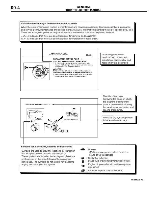
AC311239 35A-21 Classifications of major maintenance / service points When there are major points relative to maintenance and servicing procedures (such as essential maintenance and service points, maintenance and service standard values, information regarding the use of special tools, etc.). These are arranged together as major maintenance and service points and explained in detail.
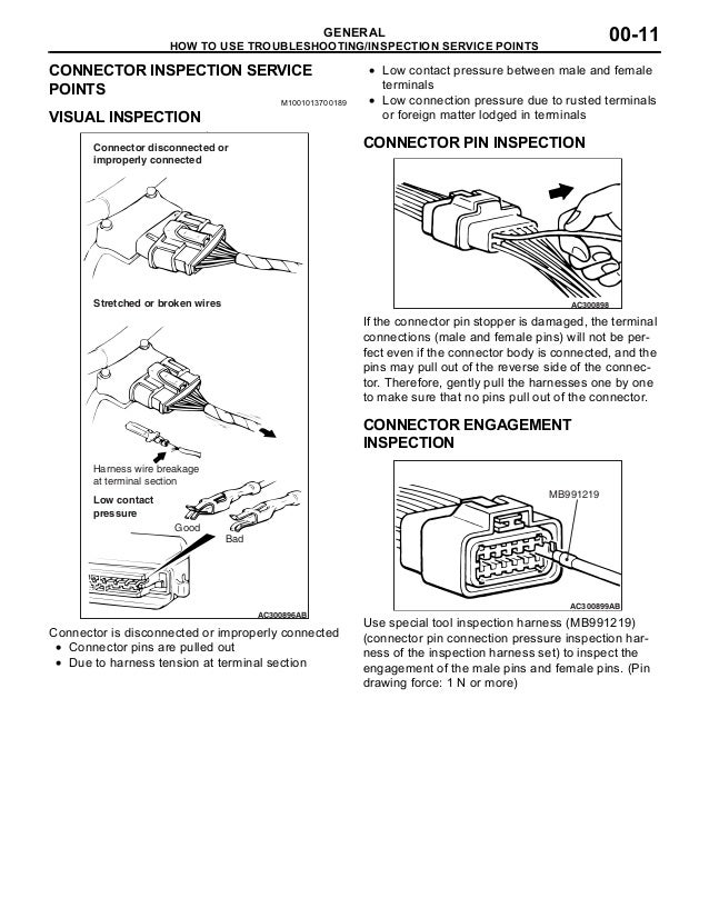
: Indicates that there are essential points for removal or disassembly. A CAUTION Never insert a test probe from the harness side, as this will reduce the waterproof performance and result in corrosion. AC105597AB Special tool Use the special tools such as test harness, harness connector or check harness. IF INSPECTING WITH THE CONNECTOR CONNECTED AC105598AH MB992006 Inspect by inserting a test probe from the harness side.


If the connector is too small to insert a test probe (e.g. Control unit connector), do not insert it forcibly. Use special tool extra fine probe (MB992006). IF INSPECTING WITH THE CONNECTOR DISCONNECTED CAUTION. Use special tool check harness (MB991219). If the test bar is inserted forcibly, it will cause a poor contact.
AC105599 MB991219 AB If the connector is disconnected, a diagnosis code may be stored for the system to be checked or other systems. Use check harness (MB991219) of special tool har- ness set (MB991223). IF INSPECTING WITH THE CONNECTOR DISCONNECTED CAUTION. Be careful not to short the connector pins with the test bars. To do so may damage the circuits inside the ECU.
Twizy Manuals Wiring Diagram
AC105600 If the connector is disconnected, a diagnosis code may be stored for the system to be checked or other systems. Touch the pin directly with the test bar.
. Keywords:.
variation based found on the Japanese Mitsubishi Diamante plus Sigma hardtop. This range was larger; more firmly built plus had more energy than its past variation. Unlike the Japanese model about that it was based this Magna showcased B-pillars more traditional springs plus shock absorbers designs plus fewer electronics. However the Australian-made TR Magna range was crafted with be exported as well as the build standard reflected this motorering aim. Like the initial generation Magna the TR model was initially an completely 4 cylinder range.
With the Australian economy nonetheless inside recession at the time there was clearly small enthusiasm for introducing a six-cylinder car. However by 1993 with all the economy recovering plus oil costs stable the TR Magna was available with a V6 engine the same engine which had been present found on the KR Verada because late 1991. The Magna family automobile of its time. TR (1991–1994). GLX guide plus car (carb only).
Executive guide plus car (Electronic Fuel Injection only). Executive V6 guide plus auto. SE guide plus car (Electronic Fuel Injection only). Elite car (Electronic Fuel Injection only) TS (1994–1996). Keywords:. F5M41 5-speed manual ● F5M42 5-speed manual ● F4A41 4-speed automatic NOTE: Regular maintenance repairs to ancillary components and removal and installation of the gearboxs are described.
Overhaul or reconditioning of the gearboxs is not covered. Gregory’s workshop manuals are produced for the Australian market.
These vehicle specifications may vary from those sold in other countries. Please be aware of these possible differences prior to using the data contained within. Covers everything you need to know step by step procedures 100s of photos and drawings routine maintenance electrical schematics repairs and overhauls and what tools to buy. Gregory’s manuals are based on an actual vehicle disassembly and are researched and written by automotive motorers with vast experience. Gregory’s workshop manuals are produced for the Australian market. These vehicle specifications may vary from those sold in other countries.

Please be aware of these possible differences prior to using the data contained within.